Generality - Principle - Applications
GENERALITY
In 1938 Olaer conceived and built the hydro-pneumatic bag-type accumulators (Mercier-Greer license). From there until its entry into the big family Parker in 2013 it remained a leader in the construction and supply of accumulators. The sizing of bag accumulators is based on the Mariotte law, which considers the important difference in compressibility between a gas and a liquid. Hydraulic accumulators are basically divided into three types. Bag, Membrane, Piston accumulators. In bag and membrane accumulators, these are blocked in the body and inflated with nitrogen at a pressure determined according to the work to be carried out and to the application. In piston accumulators the separation of gas (nitrogen) and fluid is carried out by means of a floating piston.
Types of accumulators in production:
MODELS
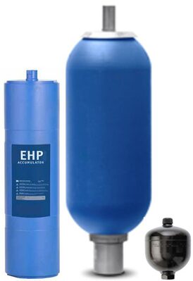
EHV Series: High pressure bladder accumulators. Forged body without welding. Fluid side anti-extrusion valve. Sturdy nitrogen loading valve. Completely removable battery for overhauling and replacement of damaged parts.
EBV Series: Low pressure bladder accumulators. Forged body without welding. Fluid side window. Sturdy nitrogen loading valve. Completely removable battery for overhauling and replacement of damaged parts.
ELM Series: Membrane accumulators with vulcanized metal anti-extrusion plate. welded steel body. Hexagonal screw for nitrogen loading. NON-repairable accumulators. in case of damage they must be replaced.
EHP Series: Gas-side flanged piston accumulators. Non-welded, bored and ground pipe. Aluminum piston. Nitrogen loading valve. Completely removable battery for overhauling and replacement of damaged parts.
ACCUMULATOR OPERATING PRINCIPLE
Operation of the gas loaded bladder accumulator is based on the considerable difference in compressibility between a gas and a liquid, enabling a large quantity of energy to be stored in an extremely compact form. this enables liquid under pressure to be accumulated, stored and recovered at any time.
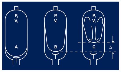
BLADDER ACCUMULATOR
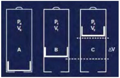
A - Bladder in the Precharge position, wich means that the accumulator only contains nitrogen. The antiextrusion system closes the hydraulic orifice which prevents the destruction of the bladder. In low pressure accumulators the bladder rests against the grid. Maximum pressure differential (P2/P0): 4:1
B - Position at the minimum operating pressure. There must be a certain amount of fluid between the bladder and the hydraulic orifice, such that the antiextrusion system does not close the hydraulic orifice.
C - Position at the maximum operating pressure. The volume difference between the minimum and maximum positions of the operating pressures represents the working fluid quantity.
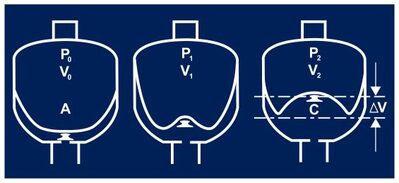
DIAPHRAGM ACCUMULATOR
A - The diaphragm is in the precharge position, wich means that it is only filled with nitrogen. The knob closes the hydraulic orifice and prevents the destruction of the diaphragm.
B - Position at the minimum operating pressure: there must be a certain amount of fluid between the diaphragm and the hydraulic orifice, such that the knob does not close the hydraulic orifice. thus, P0 must always be <P1.
C - Position at the maximum operating pressure: the volume change ΔV between the minimum and maximum positions of the operating pressure represents the fluid quantity stored.
PISTON ACCUMULATOR
When fluid under pressure enters the fluid side of accumulator, the piston is pushed towards the gas side and the nitrogen gas is compressed.
APPLICATIONS
The hydraulic accumulators is an essential component for the optimum operation of a hydraulic
circuit. In hydraulic circuits, the
accumulator enables:
Energy Storage: saves energy without
loss and redistributes when required therefore reducing installed power.
Pressure compensation: absorbs pressure spikes
from pumps or other components to control pressure and flow-rates in a
hydraulic circuit.
Volume
Control: absorbs fluid volume variations induced by temperature
changes in a closed hydraulic circuit and maintains a rated pressure.
Maintains
Fluid Flow Rate: an accumulator can maintain the fluid flow
rate in case of pump failure and can also be used as a mobile fluid reserve
under pressure.
Emergency Energy
Storage: in case of failure of the main energy source, an accumulator can
provide sufficient energy to complete an operation or to realize a full
hydraulic cycle.
Prevents
mixing of fluids: Transfer of energy from a fluid to another
fluid without any risk of mixing.
Shock absorber: suppresses shocks and
vibrations in hydraulic systems of lifting vehicles (e.g. Forklift trucks) and
maintains real suspension of the load on a gas spring.
 Download type EHV/EHVF >>
COMER ACCUMULATOR SERVICE CENTER
From 2019 COMER is officially the Parker / olaer Accumulators service center. Comer has all the appropriate equipment and large spare parts warehouse to perform checks on the preloads, internal bag replacements and interventions in general on the whole range of accumulators in production both Parker and Olaer.